Rainbow Inductance Adapter
By Chuck Hines, K6QKL
Capability to precisely measure small inductances is useful for a QRP builder. I've used a variety of methods over the years. The Heath IB-5281 RLC Bridge can get you roughly into the general vicinity. A grid dipper measuring an unknown inductance soldered across a precise, known capacitor is little better, limited by the dipper's calibration and dial. Using an RF generator, digital counter and a scope works occasionally, depending upon the coil Q, but requires a fair amount of equipment setup time. Decided to build and check out the inductance adapter published in the 2003 ARRL Handbook. Schematic is Fig. 26.23 on page 26.25 of that volume. The printed circuit and component layout are located near the top of page 30.65. {My edition contains an error in that PC layout - there are two different resistors both labeled R2. To correct that, change the label on the R2 resistor next to pot R7 to R9.} A 220 Ohm 1% resistor worked fine as R3 for me.
|
|
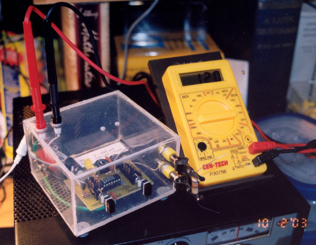
| K6QKL's Inductance Adapter. Click on the photo to view a larger image. |
Bought a PC board from FAR Circuits in Dundee, IL and the IC and other components from the usual surplus sources in St. Louis. Added a bright yellow LED in series with a 1K resistor from the power switch SW2 to PC ground so I could see when the adapter was powered from its external power supply. Cobbled together a Lucite acrylic case from 3/32" sheet stock from the hardware store. Drilled holes in that case for alignment access then, after the unit functioned and everything was verified and working properly, glued the case shut. The test clips are Grayhill 02-1 nickel-plated steel clips mounted on a standard banana plug. Fairly expensive clips but quite durable and easy to work with using only one hand. Test inductor leads slide in and remain clamped by the clip. The inductance adapter is connected to a digital voltmeter (DVM) which displays inductance values from 3 to 500 µH on the adapter low range and from 100 µH to 7mH on the high range.
Zeroing and calibration is straight forward using several known inductors. It may not be obvious but you are really calibrating your inductance adapter to work with a particular DVM. No two DVMs are likely to give identical readings on the same milliVolt range measurement. If you change the DVM you use with your adapter, go through the calibration process again. Doesn't take long to perform. The DVM in the accompanying photo is a $4.99 item from Harbor Freight Tools with which many of you are already familiar. Works quite well with the adapter. I bought a few. Idea was to pare one DVM board down to about the size of the LCD display, snip off the extra board, get rid of the case and meter functions not required, hardwire what remained, then use the tiny heap remaining as a dedicated 200 mV display powered by the same external 9 V DC source serving the inductance adapter. Haven't gotten around to doing all that as yet.
This is a simple circuit. One IC, couple switches, a voltage regulator and a few resistors and capacitors. What could go wrong? Why were builders occasionally reporting problems with the circuit and asking if anyone had ever gotten this project to actually work? Take another look at two capacitors: C1 a 0.01 µF and C3 a 0.001 µF. They sure look like standard RF bypass capacitors to us, don't they? They aren't. In this circuit C1 and C3 are components requiring reasonably precise values to produce a specific RC time constant which determines the calibration of your adapter in High and Low measurement modes. Slap in any old .01 or .001 disk capacitor and you'll risk reading really strange numbers on your DVM while calibrating. A 10% tolerance for all components is specified for the adapter. Bypass ceramic cap tolerances tend to run around -40% to +100%. Measure the capacitors you use for C1 and C3 carefully, get as close as you can to 1000 PF for C3 and 10,000 PF for C1. Reject any out of tolerance values.
This is a rather useful instrument and yes, it does actually work. Accuracy (linearity) is quite good. Instead of searching out surplus parts as I did, recommend you simply order an Inductance Meter Kit #1A-1 directly from Rainbow Electronics in Indianapolis. $14.95 plus shipping. (888-291-7262) Everything you'll need is in the kit including a well made PC board, IC, components, instructions, schematic, etc. I spent more than that on gas while searching for all the stuff that comes already packed inside the Rainbow kit.
When you have a requirement to measure inductance values smaller than 3 µH, take a look at an article by W6YBT published in QEX, May 1989, pp 11-13. Equally simple kind of adapter circuit. Feeds into a Fluke meter. Is something of a current hog. But it snuggles right in and provides reasonably accurate measurements of inductance values down to well under a tenth of a µH.
Chuck, K6QKL
October 11, 2003